WiegandDcd, decodes the Wiegand code
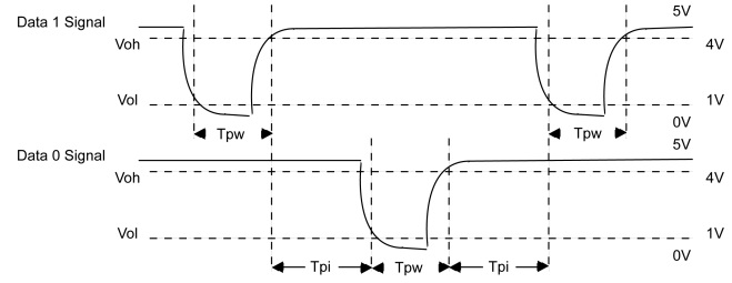
L'interfaccia Wiegand è considerata di fatto uno standard di cablaggio utilizzato per l'interconnessione di periferiche di riconoscimento, si compone di tre fili, una massa e due dati DATA0, DATA1. Le due uscite sono tenute a livello logico alto, per trasmettere "0" viene settato basso DATA0, per tramettere "1" viene settato basso DATA1.
Questo FB decodifica un codice Wiegand a 26 bits, può essere eseguito come una funzione, occorre fornire in WBCount il numero di bits che compongono il codice ed in WBData il codice Wiegand acquisito. In uscita se il codice è corretto sarà attivo CodeOk ed avremo in Facillity ed in IDNumber il codice decodificato. In caso di errore nella decodifica viene attivata per un loop di programma l'uscita Fault.
Approfondimenti
- Gestione RFiD readers da programma PLC (Forum)
- Programma gestione controllo accessi.
- In questo topic sono riportate informazioni sulla acquisizione e decodifica protocollo Wiegand.
- In questo topic si tratta l'acquisizione di più dispositivi.
- In questo topic un esempio di acquisizione due tastiere Wiegand utilizzando 4 counters.
Specifiche protocollo Wiegand
Il protocollo Wiegand a 26 bit ha ampiezza impulso Tpw compresa tra 20 uS e 100 uS ed intervallo tra impulsi Tpi compreso tra 200 uS e 20 mS. Il formato Wiegand a 26 bit standard è così suddiviso:
-
Bit 1 Even parity over bits 2 to 13
-
Bits 2 to 9 Facility code (0 to 255); Bit 2 is MSB
-
Bits 10 to 25 ID Number (0 to 65,535); Bit 10 is MSB
-
Bit 26 Odd parity over bits 14 to 25
Descrizione

| Parametro | Tipo | Descrizione |
|---|---|---|
| Enable | BOOL | Abilitazione FB, attivandolo viene eseguita la decodifica del codice. |
| WBCount | USINT | Numero bits del codice Wiegand da decodificare. |
| WBData | DWORD | Codice Wiegand da decodificare. |
| CodeOk | BOOL | Si attiva se decodifica correttamente eseguita. |
| Fault | BOOL | Attivo per un loop se errore decodifica. |
| Facility | USINT | Facility code decodificato. |
| IDNumber | UDINT | ID number decodificato. |
Esempi
Come utilizzare gli esempi
Nell'esempio viene acquisito un lettore RFID R3 connesso agli ingressi Di00 e Di01 di un modulo CPU SlimLine. Per poter campionare i segnali DATA0 e DATA1 del lettore il programma viene eseguito in task fast ad ogni 1mS. Il codice letto è ritornato in TAGID.
LogicLab (Ptp202, ST_WiegandDcd)
PROGRAM ST_WiegandDcd
VAR
    i : UDINT; (* Auxiliary variable *)
    TimeBf : UDINT; (* Time buffer (mS) *)
    Errors : UDINT; (* Error counter *)
    TAGID : UDINT; (* TAG ID *)
    Data : ARRAY[0..1] OF BOOL; (* Data status *)
    Value : ARRAY[0..1] OF UDINT; (* Counter value *)
    CInp : ARRAY[0..1] OF SysGetCounter; (* Counter acquisition *)
    WDecoder : WiegandDcd; (* Wiegand decoder *)
END_VAR

// *****************************************************************************
// PROGRAM "ST_WiegandDcd"
// *****************************************************************************
// Program performs a Wiegand code acquisition from a reader connected to the
// CPU module logic inputs. Connect DATA0 to Di00 and DATA1 to Di01.
//
// The program must be executed at least every Wiegand Tpi time, that has range
// from 200uS to 20mS.
// -----------------------------------------------------------------------------

    // -------------------------------------------------------------------------
    // INITIALIZATION
    // -------------------------------------------------------------------------
    // Program initialization.

    IF (SysFirstLoop) THEN

        // Executing the program in task Fast you can set the execution time.

        eTO_JUNK(SysSetTaskLpTime(ID_TASK_FAST, 1000));

        // Config the two CPU module counters.

        CInp[0].Address:=255; //Module address
        CInp[0].Channel:=0; //Module channel
        CInp[0].Mode:=16#00000000; //Acquisition mode

        CInp[1].Address:=255; //Module address
        CInp[1].Channel:=1; //Module channel
        CInp[1].Mode:=16#00000001; //Acquisition mode
    END_IF;

    // -------------------------------------------------------------------------
    // WIEGAND CODE DECODING
    // -------------------------------------------------------------------------
    // After a while that no data are received if the number of wiegand bits is
    // 26 the code is decoded

    IF ((SysTimeGetMs()-TimeBf) > TO_UDINT(T#100ms)) THEN
        WDecoder(Enable:=TO_BOOL(WDecoder.WBCount = 26)); //TAG decoding

        // If Wiegand data correctly decoded TAG ID is returned.

        IF (WDecoder.CodeOk) THEN
            TAGID:=TO_UDINT(WDecoder.Facility)*16#10000; //TAG ID
            TAGID:=TAGID+WDecoder.IDNumber; //TAG ID
        END_IF;

        // Initialize value for next decoding.

        WDecoder.WBCount:=0; //Wiegand bits counter
        WDecoder.WBData:=16#00000000; //Wiegand bits data
    END_IF;

    // -------------------------------------------------------------------------
    // WIEGAND DATA ACQUISITION
    // -------------------------------------------------------------------------
    // The DATA0 and DATA1 are connected to 2 CPU module digital inputs.
    // Acquires the inputs and check if they are changed.

    CInp[0](); //Counter acquisition
    CInp[1](); //Counter acquisition

    // Acquire DATA0 and DATA1. If both are not set no data is acquired.

    Data[0]:=TO_BOOL(CInp[0].Value <> Value[0]);
    Data[1]:=TO_BOOL(CInp[1].Value <> Value[1]);
    IF NOT(Data[0] OR Data[1]) THEN RETURN; END_IF;

    // Acquisition error if both are set. Probably the program is executed too
    // slowly, less than Wiegand Tpi time.

    Value[0]:=CInp[0].Value; //Digital input value
    Value[1]:=CInp[1].Value; //Digital input value
    TimeBf:=SysTimeGetMs(); //Time buffer (mS)
    IF (Data[0] AND Data[1]) THEN Errors:=Errors+1; RETURN; END_IF;

    // If DATA0 is set "0" is acquired.
    // If DATA1 is set "1" is acquired.

    WDecoder.WBCount:=WDecoder.WBCount+1; //Wiegand bits counter
    WDecoder.WBData:=(WDecoder.WBData*2); //Wiegand bits data
    IF (Data[1]) THEN WDecoder.WBData:=WDecoder.WBData OR 16#00000001; END_IF;

// [End of file]